Did you know that all Enalysis users can use Fieldlink to enter compressor field data into Enalysis? Fieldlink eliminates the need for any paper data collection or manual data input. Simply input all compressor field data into the app and Fieldlink will automatically upload the data to generate an Enalysis report. Fieldlink can be used as part of your daily routines or for occasional troubleshooting.
This post will guide you through the steps of entering compressor field data via Fieldlink® for Enalysis® for both reciprocating and screw compressors. If you require assistance with installing the app or logging in, please contact your Detechtion Engineering Account Manager directly or send an email to erc@detechtion.com.

Getting Started
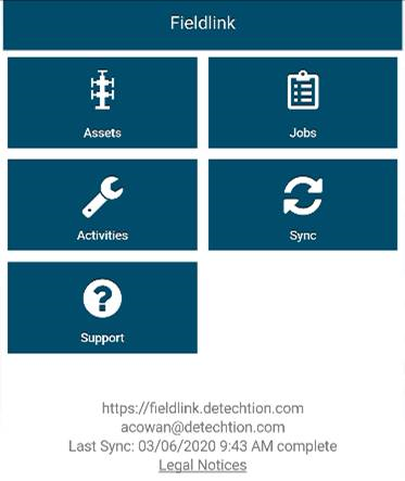
Open the DT Fieldlink app and allow the app to sync to update data from the Detechtion Technologies database. The app will work without an active internet connection, but it is recommended to allow the app to open and sync at the start of each day to capture and changes to your compressor database.
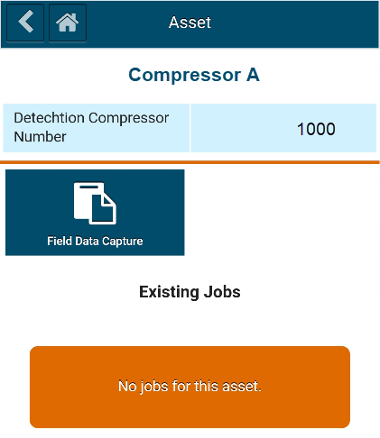
Once the app has sync’d, you will be presented with the screen shown below. To enter field data for your compressor, first select the correct compressor by clicking on the Assets button.
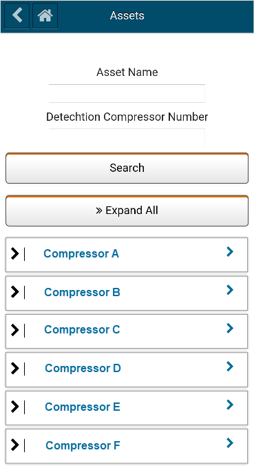
 Search for the desired compressor by the compressor name or Detechtion compressor number. By permitting the app access to your device’s location, the list of compressor below the search bar will auto populate based on the compressors closest to you current location. Select the desired compressor from the list of assets.
Click on the Field Data Capture button or select an existing job to complete a field data capture job that was started previously.
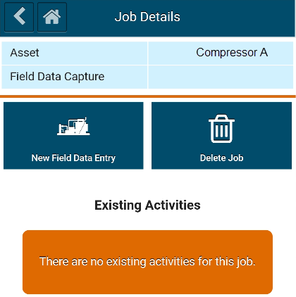
Select the New Field Data Entry to start a new field data capture for your selected compressor.
Field Data Capture - Reciprocating
Starting a New Field Data Entry job your selected compressor brings up a field data entry screen in Fieldlink that is specific to your selected compressor. Data entry is separated into the following sections:
-
Overview – Required
-
Update Overhaul / Oil Change Hours – Optional
-
Running Conditions – Required
-
Operating Conditions – Required
-
Update Cylinder Configuration – Required Only if Changed
-
Operators Notes – Optional
Overview:
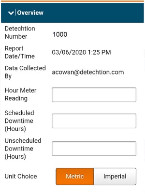 Hour Meter Reading: Total runtime on the compressor. Can be left blank if not available
Scheduled Downtime (Hours): The time, in hours, that the compressor was offline since the last Field Data Capture a planned event. Can be left blank or entered as zero if the compressor has run continuously since the last data entry.
Unscheduled Downtime (Hours): The time, in hours, that the compressor was offline since the last Field Data Capture as a result of a trip or unplanned event. Can be left blank or entered as zero if the compressor has run continuously since the last data entry.
Use the “Metric/Imperial” unit choice buttons to switch between metric and imperial units for data entry. These buttons can be selected multiple times throughout the data entry if the field data is a mixture of metric and imperial units of measure.
Updated Overhaul/ Oil Change Hours: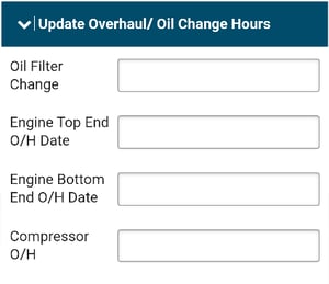
This section is used to enter date of a completed Engine or Compressor overhaul or oil change. This section can be skipped and left blank if there has not been any scheduled work completed on the compressor requiring entry into Enalysis®.
Running Conditions:
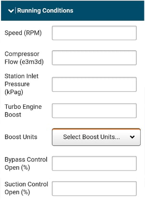
Global operating parameters. All data entry variables in this section are required.
Speed (RPM): The current engine running speed.
Compressor Flow: Compressor flow from flow meter. Please enter 0 if not flow meter is present. (E3m3/d or MMscfd only)
Station Inlet Pressure: Pressure upstream of any suction control valve. Please enter Stage 1 suction pressure if no upstream pressure is available.
Turbo Engine Boost: Engine load as indicated by turbo intake manifold air pressure or calculated panel load.
Boost Units: Please select the correct units from the Boost units drop down.
Bypass Control Open (%): Recycle valve percent open. Enter 0 if fully closed.
Suction Control Open (%): Suction control valve percent open. Enter 100 if fully opened and providing no restriction to flow from the field.
Operating Conditions:
This section is cylinder specific and all data entry variables are required. The cylinders of the compressor are listed in order of Stage and Throw number.
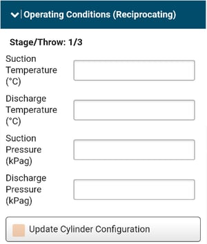 Temperatures (Suction/ Discharge): Ideally taken from a digital temperature transmitter, but an IR-gun is preferable to analogue temp gauges if digital temperature transmitters are not installed. One suction temperature per stage is required, while the discharge temperature of each cylinder is required.
Pressures (Suction/Discharge): Suction and Discharge pressures are required to be entered for each cylinder. Ideally, a suction and discharge pressure reading is taken for each stage. If an interstage (Stage 2, 3, etc) suction pressure is not available, then the previous stage discharge pressure can be entered, assuming negligible pressure drop between stages.
Updated Cylinder Configuration: This button provides the ability to update the cylinder configuration; including cylinder action, VVCP pocket position, and any added clearance spacers. If no change has been made to the compressor configuration, then no action is required and the previous cylinder configuration from the last Enalysis® report will be used.
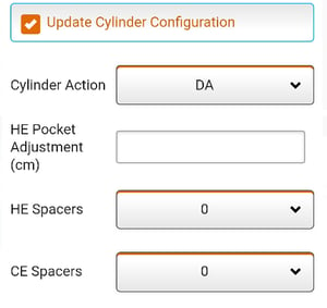 Cylinder Action:
Operator Notes: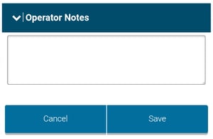
This section provides an opportunity to communicate any additional information pertinent to this compressor or set of field data. The comments will be entered into the Operator Log in Enalysis®, as well as included in the main body of the Enalysis® report email.
Save:
Click Save to complete the data capture. The captured field data will be cached in your device and sync’d when the device has a mobile or Wi-Fi data connections to generate an Enalysis® report.
Field Data Capture – Rotary Screw
All sections of the rotary screw field data capture are the same as described above for the reciprocating compressor, except for the operating conditions.
Operating Conditions: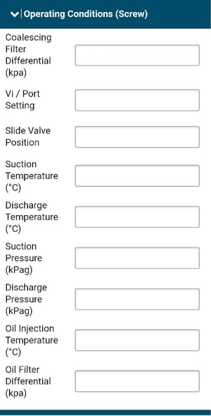
This section is specific to the rotary screw compressor and all data entry variables are required.
Coalescing Filter Differential Press: The pressure differential across the discharge coalescing filter element. This can be entered a 0 if no gauge is present.
Vi / Port Setting: Enter the current Vi setting for screw compressors with a variable Vi.
Slide Valve Position: Current position of the slide valve.
Temperatures (Suction/Discharge): Ideally taken from a digital temperature transmitter, but an IR-gun on the suction/discharge piping is preferable to analogue temp gauges if digital temperature transmitters are not installed.
Pressures (Suction/Discharge): Suction and Discharge pressures are required. Ideally, the suction pressure should come from the suction piping as close to the inlet of the screw as possible. Discharge pressure should be taken from the discharge line upstream of the coalescing filter.
Oil Injection Temperature: Temperature of the oil immediately before it enters the screw compressor. If no digital gauge is present, an IR temperature gun can be used to shoot the piping of the oil circuit. The correct location is downstream of the oil filter and towards the discharge end of the screw compressor casing.
Oil Filter Differential Pressure: The pressure differential across the oil filter element. This can be entered a 0 if no gauge is present.
Click here to read Enalysis Tip 1.10 - Reciprocating Compressor Limitations now!