Reciprocating compressor packages are restricted to operating under conditions that ensure the mechanical ratings of the compressor are not exceeded. Exceeding one or more limits of the compressor can result in catastrophic failures requiring expensive repairs and resulting in costly downtime.
Key limits of a reciprocating compressor include, but are not limited to, rod loads (static and dynamic), degrees of reversal at the crosshead pin, net ratios and volumetric efficiencies. Additional considerations include the lowest maximum allowable working pressure, MAWP, and rated temperature of all components and vessels for each stage of compression. Finally, all compression must be accomplished within the rated power limits of the drive power source, commonly a gas driven engine or electric motor.
The primary limitations encountered with reciprocating compressors are explained in detail below.
Power and Speed Limitations
The compressor frame and the coupled power source (natural gas driver, electric motor, turbine, etc.) both have maximum power and speed limitations set by the manufacturer. To promote safe and reliable operation, it is essential to adhere to these limitations. The driver power capacity is often the limiting factor with the compressor frame commonly having a power rating greater than the accompanying driver.
In good compressor package design, both the compressor and the driver should be rated to the same maximum operating speed. For compressor packages where the driver and the compressor have different rated running speeds, the package must never be operated above the lowest rated speed.
Most compressors come with one or more modes of capacity control, which can be implemented to increase throughput when power limitations have been reached. The most common form of capacity control when operating with high power demands included:
- Variable (VVCP) and/or Fixed Volume Clearance Pockets (FVCP)
- Valve Clearance Spacers
- Single-Acting one or more cylinders
- Fixed Clearance Plugs
- Cylinder or Stage Blow Through
In addition to the items above, other forms of capacity control can also be utilized in low flow and low power operating ranges. These included, but are not limited to:
- Operating Speed
- Controlling/Varying Suction Pressure
- De-activating Cylinders/Stages
- Recycle Valve Operation
It is also important to take note of any minimum power or speed restrictions provided by the manufacturer. Minimum operating speeds ensure that the rated torque levels can be achieved, and that proper circulation of oil and coolant occurs within the driver. Operating above minimum power limits helps to avoid glazing of the cylinders. Operating at low power requirements can often lead to increased maintenance requirements.
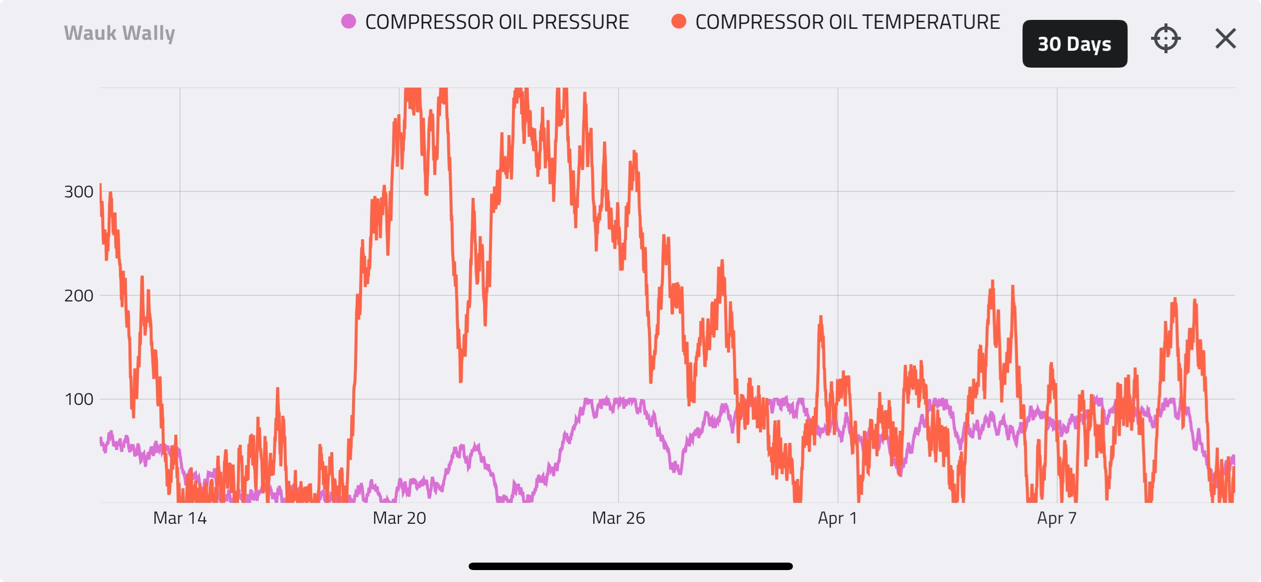
Maximum Allowable Discharge Temperatures
During the compression process the temperature of the gas will increase. Although many factors contribute to the resulting final discharge temperature, the three most influential are the inlet suction temperature, compression ratio, and gas composition.
Inlet Suction Temperature:
- Increasing inlet suction temperature results in a higher discharge temperature
- Decreasing inlet suction temperature results in a lower discharge temperature
Compression Ratio:
- Large compression ratios result in elevated discharge temperatures
- Smaller compression ratios result in lower discharge temperatures
Gas Composition:
- Gases with lighter molecular weights have a higher ratio of molar specific heat capacities and result in a higher discharge temperature
- Gases with heavier molecular weights have a lower ratio of molar specific heat capacities and result in a lower discharge temperature
In standard practice, it is advisable to never exceed operating discharge temperatures of 176.7°C (350°F), however, many compressor packages will consist of components limiting discharge temperature to no more than 148.9°C (300°F). The discharge temperature of each stage must never exceed the material temperature limits of any discharge component, including, but not limited to, the cylinder, piston, piston rings, rider bands, discharge valve plates, discharge pulsation bottles, discharge piping, and air-cooled heat exchange tubing.
Maximum Allowable Working Pressure
Components in a compressor package designed to contain gas are rated to a maximum allowable working pressure, MAWP. The MAWP is based on the design and material limits of the component and are specified at a maximum temperature limit. Pressures in any stage of compression must not exceed the lowest MAWP of any component used in that stage. Components with the lowest MAWP are often, but not always, the compressor cylinder, discharge pulsation bottle or the air-cooled heat exchanger.
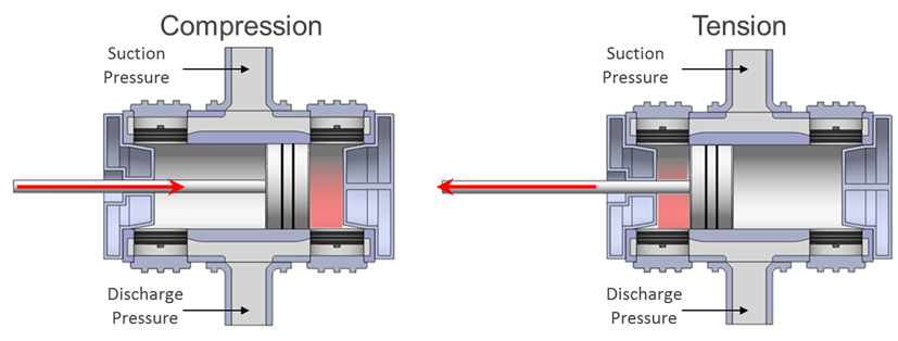
Maximum Allowable Rod Loads
Pressures acting on the surface area of the head-end and the crank-end of a compressor piston result in a load applied to the piston. The maximum allowable compression and tension rod loads are a function of the rod diameter, compressor stroke and rod material and are called Static or Gas Rod Loads. High pressures and compression ratios will result in elevated rod loads.
To ensure reliable compressor operation, it is imperative to operate below the maximum allowable compression, tension and total combined rod load limits defined by the manufacturer. When compressors with large pistons are operated at high speeds and/or low compression ratios, it may be necessary to calculate the Dynamic or Net Rod Loads, which include the gas rod loads and the inertial rod load resulting from the reciprocating masses. Compression and tension net rod load limits are provided by the manufacturer.
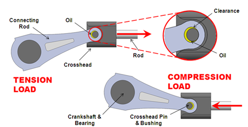
Low Degrees of Rod Reversal
Each time the net force on the piston rod switches from compression to tension or from tension to compression, this is referred to as a cross-head pin reversal or, more simply, a reversal. It is essential that two reversals occur every full rotation of the compressor crank shaft in order to achieve proper lubrication of the cross-head pin.
Reversals are measured in degrees of rotation of the crankshaft and Detechtion Technologies recommends operating with a minimum of 70° of reversal in order to exceed all manufacturers’ minimum requirements. Although rod reversals will usually remain high under normal double-acting (compressing on both the head-end and crank-end of the cylinder) operation, the following occurrences will result in a decrease in reversals:
- Single-Acting Cylinders
- Low RPM
- Damaged Discharge Valves
- High Compression Ratios
- Low Volumetric Efficiencies
- Small Cylinder Bores with Large Piston Rods
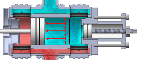
Low Volumetric Efficiencies
The volumetric efficiency of a cylinder is the ratio of actual cylinder capacity to piston swept volume. Therefore, it is essentially a measure of the proportion of the stroke that is being used to draw new gas into the cylinder and has a direct influence on the opening and closing of the compressor valves. In operating scenarios with volumetric efficiencies less than 20%, valves may not have sufficient time to fully open before the piston reaches the end of its stroke. This will result in the valve being slammed shut and decreasing overall valve life.
The volumetric efficiency of a cylinder is influenced by the mechanical clearance of a cylinder (any volume not swept by the piston), compression ratio and gas composition. ISO13631/API11P standards state that, in all cases where clearance volume is added to a compressor cylinder end, the volumetric efficiency shall not be reduced to less than 15%.
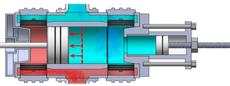
Compression Health - Blowby
Blowby is an indication of the health and efficiency of the valves and piston rings inside each cylinder. It is a term used by Detechtion Technologies to quantify inefficiencies in the compression process and is a measure of the number of molecules of gas that are being re-circulated and recompressed within a cylinder. As more gas is re-circulated and recompressed, the temperature rise across the cylinder increases, more horsepower is required and the cylinder’s capacity to compress gas decreases.
Although blowby is not actually a limit of a compressor, the presence of blowby will often result in the compressor reaching a limit prematurely as a result of elevated suction pressures and/or discharge temperatures on the affected stage. In addition, blowby can signify damaged discharge valves, which can lead to loss of crosshead pin reversals and additional damage to the compressor.
Click here to read