Changes in operating conditions, such as discharge pressure, flow rate, inlet suction temperature or ambient air temperature, will result in a variations of compressor performance. When the changes are substantial, the mechanical limits of one set of operating conditions may infringe on the normal expected parameters under alternative operating conditions. Therefore, compressors require a safety system designed to shutdown the compressor prior to the breach of any design limit.
Compressor Safety Shutdown Systems
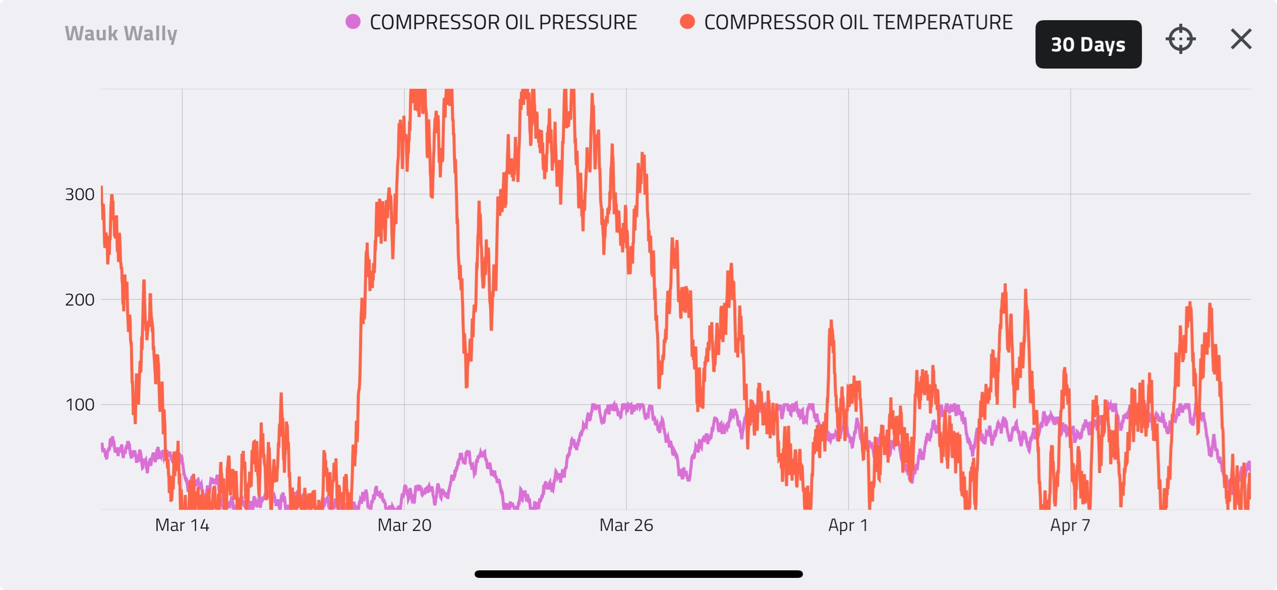
Compressor safety shutdown systems consist of pressure, temperature and vibration sensors combined with a set of annunciators and switches. Alarm and shutdown triggers are applied to critical sensors to prevent operating under any conditions that would exceed compressor rated limits. Alarms provide a warning to an operator that a limit is being approached, while triggering a shutdown will immediately cease the operation of the compressor.
Requirements of these shutdowns, alarms, annunciators and switches are standardized by ISO13631/API11P. Although the requirement laid out in the standards are specific, the application is quite general. Relevant excerpts of the ISO1361 standards are provided below.
ISO 13631:2002
Shutdowns, alarms and annunciators
14.1 General
An alarm/shutdown system shall be provided which initiates an alarm if any one of the conditions specified by the purchaser as alarm conditions reaches an agreed alarm level. This system shall also initiate shutdown of the compressor when any of the conditions specified or recommended as shutdown conditions reaches an agreed shutdown level. Shutdown and alarm systems shall be designed to operate in a fail-safe mode.
The systems may function hydraulically, pneumatically, electrically or in any combination, as specified by the purchaser.
Unless otherwise agreed, for every shutdown function an alarm function shall be provided and set at a value which represents a deviation from the normal condition and less than the setting of the shutdown. Additional alarms, not associated with shutdowns, shall be provided as specified.
14.2 Minimum required shutdowns
The conditions at which shutdown is required, as a minimum, are specified in Table 7.
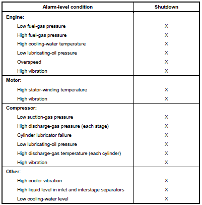
Figure 4: ISO 13631 Table 7 – Minimum shutdown requirements
14.3 Additional alarms and shutdowns
The extent to which the alarm and shutdown systems shall be supplied by the vendor shall be specified by the purchaser on the data sheets.
14.4 Annunciators
Each component which actuates an alarm or a shutdown shall also actuate an annunciating device which indicates first-out cause of alarm or shutdown. Annunciators shall be bypassed only for the purpose of a preset-time lock-out for use on certain shutdown devices during start-up and manual testing. The vendor shall specify the type and size of annunciator, the shutdowns and alarms to be annunciated, the number of spare points on the annunciator panel and the type of warning (audible or flashing light or both) for alarms and shutdowns.
14.7 Shutdown and alarm settings
Shutdown and alarm settings shall be mutually agreed upon by the purchaser and vendor.
Shutdown and Alarm Settings
Changes in operating conditions will result in corresponding changes to the pressures and temperatures in a compressor. When the changes are substantial, the mechanical limits of one set of operating conditions may infringe on the normal expected parameters under alternative operating conditions. Special consideration must be given to these situations to ensure that the compressor safety shutdown system is able to protect the compressor over the entire operating range.
The protection of any compressor meeting the minimum requirement for safety shutdowns, as specified by ISO13631/API11P, depends on the static shutdown trip settings on the following monitored process parameters:
- Low (Stage 1) suction-gas pressure
- High discharge-gas pressure (each stage)
- High discharge-gas temperature (each cylinder)
A safety shutdown system consisting of only the minimum shutdowns requires the low (Stage 1) suction-gas pressure and high discharge-gas pressures (each stage) to be set to protect the compressor from exceeding all compressor limitations, other than maximum allowable temperature, previous described. Therefore, these settings will often be conservative for normal operating conditions, thus restricting the permissible operating range. For example, a compressor that normally discharges into a pipeline at 8000kPag may not reach rod load limits until the inlet suction pressure has declined to 300kPag. However, the low suction-gas pressure may be limited to only 800kPag, as rod load limits would be reach at this pressure at the pipeline’s maximum operating pressure of 10,000kPag.
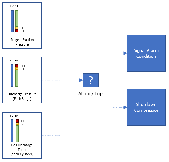
BASIC SAFETY SHUTDOWN AND ALARM SYSTEM
The limitations to the operating range can be reduced by adding alarm and shutdown settings on the following monitored process parameters:
- High (Stage 1) suction-gas pressure
- Low discharge-gas pressure (each stage)
- Differential Pressure (each stage)
Shutdowns on these process variables provide increased protection against high rod loads and low volumetric efficiency. This permits a greater overall compression ratio between the low (Stage 1) suction-gas pressure and the High discharge-gas pressure shutdowns, as the focus of these shutdowns shifts towards material limits of the components, such as MAWP. This results in an increase to the permissible operating range of the compressor under most scenarios.
A diagram of a standard safety shutdown and alarm system is shown below.
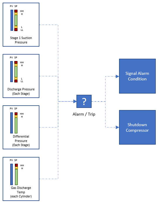
STANDARD SAFETY SHUTDOWN AND ALARM SYSTEM
There are two common philosophies for setting the high discharge-gas temperature trip point for each cylinder:
- Trip set to lowest maximum rated temperature of the stage. This is often the rated operating temperature of the valve plate material but can also be the rated temperature of a discharge vessel (cooler, piping, pulsation bottle) when PEEK high-temperature valves are used.
- Trip set to small margin above the normal operating temperature. This will provide for early protection against valve failures and/or process upsets.
While the latter philosophy provides superior protection, the former will result in a broader operating range and a reduction in compressor trips. The correct philosophy for any compressor will depend on the instrumentation and communication systems present and the type and extent of condition monitoring conducted.
Control System - Suction and Recycle Valve Setpoints
While the purpose of the safety shutdown system is to prevent the breach of any design limit, control points are used to prevent process variables from reaching their shutdown trip, thereby maintaining safe and continuous operation of the compressor. Control points are most commonly set on the following process variables:
- Low (Stage 1) suction-gas pressure
- High (Stage 1) suction-gas pressure
- High discharge-gas pressure (final stage, PSHH)
Whereas alarms are set at a margin to each shutdown trip point, control points are set at a margin from the first acting shutdown trip point. For example, if declining suction pressure will result in high discharge temperature before any other limit is reached, then the low control point will be set at a pressure to prevent the maximum rated discharge temperature being exceeded. Reaching a control point will modulate the suction control or recycle valve or, in some instances, reduce the driver speed. The function of these two valves, combined with variation in driver speed, is to maintain an operating range within that defined by the safety shutdown shutdowns.
The suction control valve regulates rising suction pressure with increasing flowrates and primarily serves to protect against driver power limits and high Stage 1 rod loads. The recycle valve maintains suction pressure with declining flowrates and primarily protects against rising discharge temperature, high rod loads and low volumetric efficiencies. Reduction in the driver RPM serves to reduce compressor capacity in order to prevent further declines in suction pressure or increases in discharge pressure due to excessive pipeline packing. A standard configuration of a suction control and recycle valve is shown in the schematic below.
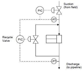
COMPRESSOR SUCTION CONTROL AND RECYCLE VALVE SCHEMATIC
The control points should be treated as the primary defense of a compressor against an upset in process or machine conditions. If the controller is unable to respond to the process upset, an alarm follows and alerts of an approaching limit. Should the upset worsen, the final defense of the compressor is the safety shutdown trip.
The following two diagrams illustrate a traditional capacity control approach for both the suction control and recycle valves.
Capacity Control – Driver RPM and Recycle Valve
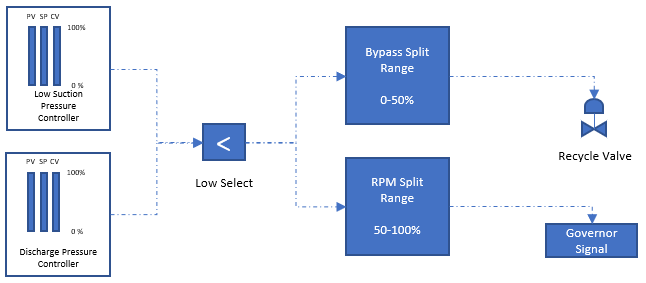
EXAMPLE CAPACITY CONTROL LOOP
The control loop shown in this flow diagram aims to maintain a predetermined minimum suction pressure despite declining upstream deliverability or to reduce compressor throughput to limit increases in discharge pressure caused by excessive line packing. In order to minimize fuel gas or electricity usage, the primary response is a reduction in driver speed. If the driver speed is reduced to the minimum rated speed, the secondary response is to open the recycle valve. If the control value results in the driver operating at minimum RPM and the recycle valve fully open, then the control system may be unable to prevent a shutdown condition being reached and tripping the compressor.
Capacity Control – Suction Control Valve
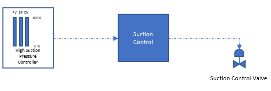
EXAMPLE SUCTION CONTROL VALVE LOOP
The high suction pressure control setpoint is set to protect against overloading the driver and from exceed Stage 1 rod loads. If the setpoint is reached, the controller will send a signal to the suction control valve to close. This will limit the capacity of the compressor and prevent further increases in the Stage 1 suction pressure.
The next Enalysis Tip will cover Detechtion Technologies’ recommended procedure for determining the shutdown and alarm settings, as well as set points for the recycle and suction control valves. Click here to read it now.