The first part of our Compression Basics series, Gas Properties, introduced key principles and the gas compression laws. It concluded by showing how gas properties and laws can be used to explain the effects of suction pressure and suction temperature on compressor throughput. The second part of this series looked at the role compression plays in natural gas production and provided some background information on two of the most common types of compressors used in natural gas gathering, the reciprocating compressor and the rotary screw compressor.
This E-Tip will look at the compression cycle for a reciprocating compressor. In addition to explaining the compression process, it will introduce the concept of unswept clearance volume in the cylinder, which will be important in the next E-Tip in this series, where we will evaluate compressor capacity.
Pressure Volume Diagrams
The reciprocating gas compressor operates on the basic principle described in Boyle’s law: it increases the pressure of a given quantity of gas by reducing its volume. Pressure-volume diagrams can illustrate the process. The horizontal line in the P-V diagram represents the changes in volume produced by the movement of the piston. The vertical line represents the pressure inside of the cylinder in relation to the changing volume.
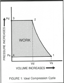
Figure 1 is a P-V diagram that represents the ideal compression cycle. The compressor cylinder fills with gas at inlet pressure (Ps) and compresses the gas to discharge pressure (Pd ) along line 1-2. Notice that all of the gas is displaced. In actual operation, it is impossible to discharge all of the compressed gas due to clearance.
Clearance is the volume of space not covered by the piston stroke and is usually expressed as a percentage of the volume displaced by the piston. Cylinder clearance includes the area between the cylinder and the head end of the piston, and the area around the valves. Clearance is unavoidable since the piston cannot touch the head, and some space must be maintained around the valves. For the standard cylinder, normal clearance will range from 4% to 20% for most standard cylinders.
Compression Stroke
Figure 2 shows a P-V diagram where clearance is taken into account. On the theoretical P-V diagram in Figure 2, point 1 is the start of compression. The cylinder is full of gas and both the inlet and discharge valves are closed.
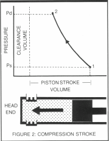
The compression stroke takes place between point 1 and point 2. As the piston moves to the left, the original volume of gas is reduced, and the pressure increases until it reaches discharge pressure.
Discharge Stroke
In Figure 3 the piston is completing the compression stroke. The discharge valves open just beyond Pd at point 2 and compressed gas flows out through the discharge valves along line 2-3.
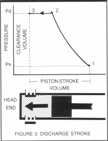 After the piston reaches point 3, the discharge valves close leaving the clearance space filled with gas at discharge pressure.
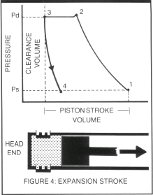
Expansion Stroke
Beginning the expansion stroke, Figure 4, both the inlet and discharge valves remain closed. As the piston moves to the right, the gas trapped in the clearance space increases in volume causing reduction in pressure. The cylinder pressure continues to decrease as the piston moves to the right until it drops below the inlet pressure at point 4.
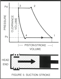
Suction Stroke
The suction or inlet stroke is illustrated in Figure 5. The inlet valves open and gas flows into the cylinder. At point 1 the inlet valves close and the compressor is ready to repeat the compression process. Line 4- 1 in the P-V diagrams represents the actual capacity of the compressor. Actual capacity is the quantity of gas that the compressor actually takes in, compresses and delivers to the discharge line. This capacity is normally expressed in cubic meters per minute or cubic feet per minute and is measured at the compressor inlet conditions of pressure and temperature. Actual capacity can be converted to million standard cubic feet per day (MMscfd) or decs (E3m3/D) to describe the amount of gas the compressor moves at standard conditions.
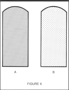
 When discussing capacity, it is important to remember that a gas always occupies all the space available to it. As a result, there can be two containers of equal volume which contain different amounts of gas. In Figure 6, the volumes of vessels A and B are identical, but there is actually more molecules of gas in vessel A. This concept was discussed in the E-Tip on Compression Basics 1 – Gas Properties. Compressor capacity increases with increasing suction pressure because more molecules of gas can occupy the cylinder volume at higher suction pressures.
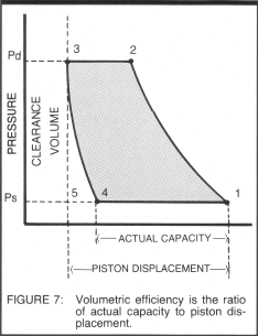
 In Figure 7, the distance between points 5-1 represents the piston displacement. This is the swept volume actually displaced by the compressor piston at rated machine speed as it travels the length of its stroke from the head end to crank end. This volume is usually expressed in cubic meters per minute or cubic feet per minute. Note that the actual capacity, points 4-1, is always less than the piston displacement. As mentioned above, this is the result of gas trapped in the cylinder clearance volume.
In the case of the double-acting cylinder, the displacement of the crank end of the cylinder is also included. The crank end displacement is less than the head end displacement by the amount the piston rod displaces.
For multi-stage units, the piston displacement of the first stage is often used to describe the piston displacement of the entire machine. The displacement of the higher level stages have a direct impact on the displacement of the first stage. However, the gas must be compressed by the first stage before it can enter the higher level stages to be compressed to the discharge line.
In the next E-Tip in this series, we will explore the key components in determining reciprocating compressor capacity.