Enalysis includes a full-featured compressor simulator for all active units enrolled in the software. The simulator uses the same calculations and compressor set-up information already in place within Enalysis to simulate the compressor’s performance at operating conditions that you input. The simulator is available 24/7 to run “What if…?” scenarios and provide instant insight into how your compressor will respond to changing conditions. Clear warnings and flags ensure operation will be safe and stable while allowing you to get the most out of your natural gas producing assets. The simulator works with any make, model or vintage of reciprocating or rotary screw compressor.
To use the simulator, simply click on the “Simulate” icon under the Enalysis asset search or the asset toolbar once an individual compressor has been selected.
 After accepting a legal disclaimer, you will be taken to the simulation screen to start modelling your selected compressor.
Reciprocating Compressors
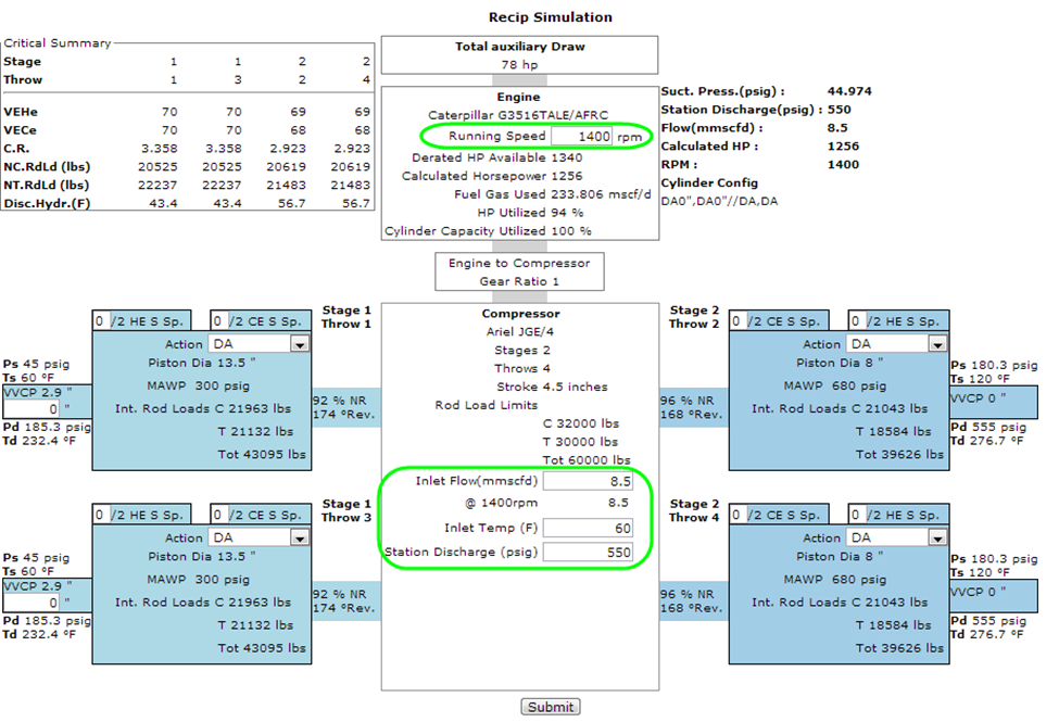
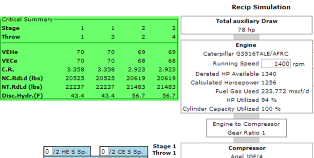
The core input values required to run a simulation on a reciprocating compressor are: Running Speed (RPM), Desired/Expected Flow, Inlet Gas Temperature and the Discharge Pressure. These are circled in green in the view of the simulator below. All other required input values are accounted for in the unit setup within the Enalysis database.
The inlet flow and discharge pressure are imported from the latest Enalysis report for the selected compressor, however, both can be changed to any value that you would like to model.
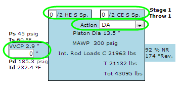
In addition to the core inputs, you can also fine-tune the simulation on a cylinder-by-cylinder basis. The cylinder action can be changed, and the clearance can be adjusted via any installed variable-volume or fixed-volume clearance pockets. Valve spacers and pre-configured load steps are also supported.
Ensure that you review the cylinder action, pocket position, spacer configuration and operating RPM to verify that the simulation represents the scenario you are trying to model:
Once you have configured the simulation as you would like to see it, simply click “Submit” at the bottom of the simulation and the output will be calculated. The key calculated output values include:
- Suction pressure
- HP/KW used for compression and auxiliaries
- Fuel gas usage
- Cylinder-by-cylinder:
- Suction and discharge pressures
- Discharge temperatures
- Volumetric efficiencies
- Compression ratios
- Rod load values (plus degrees of reversal and net ratios)
- Hydrate warnings
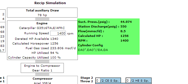
The calculated values appear at the appropriate location on the compressor diagram and in a summary section of the most relevant calculated and input values included in the top-right corner of the simulation:
Other key calculated values appear on the top-left corner of the simulation, in the “Critical Summary” table:
The “Critical Summary” table shows the calculated values of the Volumetric Efficiencies on the Head end and Crank end, Compression Ratio, Net Compression and Tension Rod Loads, and the discharge hydrate formation temperature.
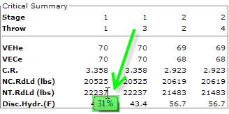
When holding your mouse cursor over any of the rod load values on the simulation, the percentage rod load relative to the rated limit will appear next to the value for easy reference:
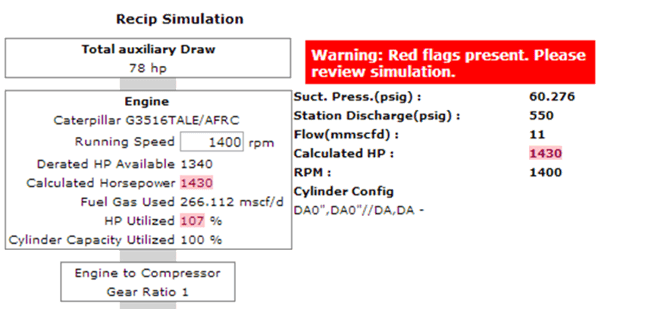
 It is also important to note that any value calculated outside of a safe or normal operating range will flag in yellow or red, depending on the severity, to ensure that the issue is addressed. When any value on the simulation is flagged in red, a warning will also appear above the summary section:
 Below the simulation are notes, assumptions, a terminology legend and further information to aid in the understanding of the simulation:
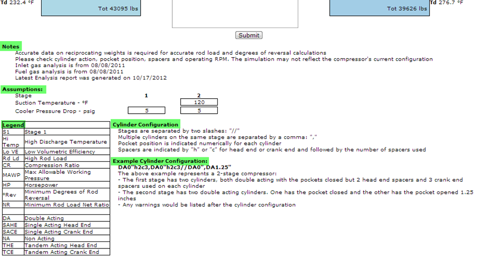 The notes section alerts you to the age of the inlet and fuel gas analyses being used by the simulation. The accuracy of the simulation will be compromised if the gas composition in the field is different than what is stored in Enalysis. The gas analysis date will be highlighted in yellow if it is more than three years old, indicating that an updated gas analysis would be beneficial.
Rotary Screw Compressor
Enalysis simulation can also be used to model the performance and limits of your rotary screw compressors. The simulation screen below shows all the core input values highlighted in green:
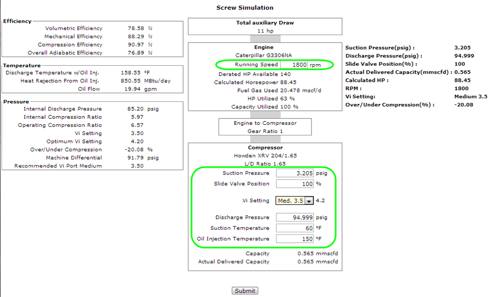
The core inputs are the Running Speed, the Suction Pressure, Discharge Pressure, Slide Valve Position, Volume Ratio (Vi) setting (if applicable), Suction Temperature and the Oil Injection Temperature. All other required information is pulled from the Enalysis unit setup.
The suction and discharge pressures are automatically imported from the latest Enalysis report, however, both values can be changed to any value that you choose to model. Make sure you also review the slide valve position, Vi setting and operating RPM on the simulation to make sure they accurately reflect the operating scenario you are trying to model.
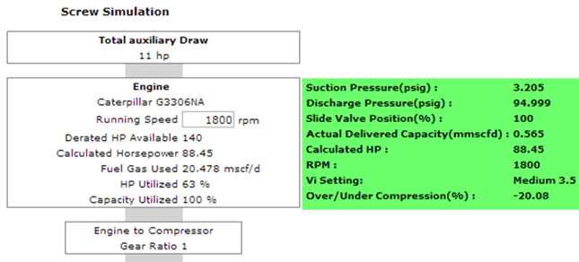
Once you have configured the simulation as you would like to see it, simply click “Submit” at the bottom of the simulation and the output will be calculated. The key calculated output values include:
- Capacity (flow)
- HP/KW used for compression and auxiliaries
- Fuel gas usage
- Over/Under compression
- Optimum and recommended volume ratio (Vi) setting
- Discharge temperature
- Efficiencies
The calculated values appear in the left-hand column of the simulation and in a summary section in the top-right corner, which also reflects your key input values:
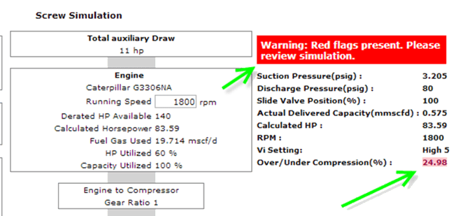
 It is also important to note that any value calculated outside of a safe or normal operating range will flag in yellow or red, depending on the severity, to ensure that the issue is addressed. When any value on the simulation is flagged in red, a warning will also appear above the summary section:
 Below the simulation are important notes and a terminology legend to aid in the understanding of the simulation:
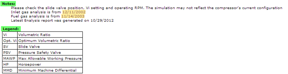
The notes section alerts you to the age of the inlet and fuel gas analyses being used by the simulation. The accuracy of the simulation will be compromised if the gas composition in the field is different than what is stored in Enalysis.
Unit of Measure (Metric / Imperial)
Like all other features in Enalysis, units of measure can be swapped between Metric (M) and Imperial (I) using the buttons in the top toolbar next to your company logo. Switching between metric and imperial will convert all values on the simulation into the appropriate units of measure:

Enalysis Simulation Warning
Please contact your Engineering Account Manager at Detechtion if you are interested in taking advantage of the Enalysis simulator.
When simulating any scenario with the new Enalysis tool, contact your Engineering Account Manager at Detechtion prior to making any physical or operational changes to the compressor to ensure that all elements are properly accounted for.
The next E-Tip will introduce the default YELLOW (Warning) and RED (Severe) flags used in Enalysis to identify compressor limits. Click here to read E-Tip 1.15 Enalysis Default Flagging Limits for Reciprocating Compressors now.
For more E-Tips, please visit the Detechtion Technologies Learning Center.